Archive for December, 2008
Where to next?
Thursday, December 25th, 2008I’m in a quandry. I really don’t know what to do. I know I’m going to be taking off all of my plastics (including the new ramp and the entire bookcase assembly) to renew them, change all the rubbers, put in some coloured light bulbs where I think they would have a great affect and tumble all of the metal parts so that they really shine, but I really don’t know what to do with the playfield.
I really would like to completely renovate the playfield, but in so doing would require me to take off more of the playfield parts than I would like and it would also take me much longer than I had planned for all of this.
So what do I do?
I will, of course, repair the mess under the ball-drop in the right flipper lane as best I can and build in protectors at all out-holes, but what about the mansion and magnet burn? I’m hoping that by polishing the playfield where the burn is with Novus 3, the oxidised paint can be removed – we’ll have to see. If not, my options will be to leave it or buy a magnet-burn decal to cover this area. Whereas I like this simple idea, unfortunately to do so will mean me having to remove the mylar from the middle left of the playfield. Even though I’ve now got some magic Goo Gone, I’m still in two minds about taking this route.
Also, for the damaged playfield in the magnet burn area and the mansion, I could touch the areas up with acrylic paint, but how long would that stay repaired? Would I be better off protecting this repaired this with a new mylar? Or should I buy one of the mansion overlays available? If I did buy an overlay, how would this react at the ‘dimples’ in the surface where the plastic covering the inserts is worn away?
So many questions and just not enough answers……yet.
Problem solved!
Thursday, December 18th, 2008Got back from a trip to the US today. And brought with me some “Goo Gone” (which is apparently very good for removing mylars – according to several articles on the internet) an imperial sized “stumpy” ratchet set (for getting to those hard-to-get places in the pinball machine), a cutter bit for my “Dremel” equivalent and some Fairchild Semiconductor QVE11233 Optos.
I couldn’t wait to test my theory on the opto switch board and so changed the Thing-Up opto. This wasn’t as easy as it could have been, as two of the pins on the opto are soldered on the backside to a very small solder pad. These pads connect through the board to the upper side of the board where connections are made to other parts on the board. When de-soldering pins from such a small pad great care needs to be taken not to overheat the pad itself otherwise it’s easy to “burn off” the pad. I did this on one of the pads which then left me with just a small section of pad to solder the new opto to. I managed it though.
Having soldered the opto in place I connected up the board and tested it……
No more switching of the Thing Up opto when the left outlane switch was activated! A success!!
Time to sit back and decide how to proceed further with my renovation.
Finding the culprit
Sunday, December 14th, 2008After a couple of days thinking about the opto board, I’m more confused than ever. It turns out that the “overheating” of the diode reported earlier, was in fact the two resistors getting hot to the touch (is this normal for a resistor, rated at 1/2 watt but only dissipating 350mW?)
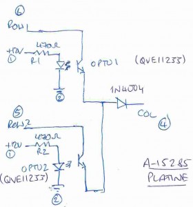
Not being able to find the schematic of the opto board in any of my manuals, or on line, I drew my own.
Whereas I can understand how this circuit works, I can’t tell why a switch connected to the adjacent column of the same row as the opto 2 “switch” should cause the opto 2 switch to effectively turn off (a similar experiment with the adjacent column switch attached to the same row as opto 1 yielded no problem).
Could it be that opto 2 was working at its limits and being affected by the slightest change in current and or voltage at its transistor terminals? Having read on the internet that some variants of the S-1865 opto was susceptible to “gain” issues causing problems in other machines, I though that this might be the problem. So it was time to find a replacement for the S-1865….
It turns out that the S-1865 was made by a company called Senisys, who, it would appear, no longer exist. Further investigations yielded that there is, however, an equivalent from Fairchild Semiconductors called the QVE11233.
A quick look on the internet revealed the data sheet for this part (on Fairchild’s website) and it looked to be the same part, although on closer examination I once again got confused (obviously an easy thing to do): on the opto board, the pcb has a marker on one of the corners of the opto which aligns to a groove on the Senisys device. I assumed this to be pin 1. This also seemed to correspond to the QVE11233 datasheet’s designation of pin 1. However, if this were in fact pin 1, my circuit diagramme would be totally incorrect (with the diode and transistor being swapped) which makes absolutely no sense to me whatsoever. If it were to signify pin 3 (or the pin out on the data sheet is incorrect) however, everything would match with my schematic.
So I’ve now ordered some QVE11233s on the internet to see how they really look like and to try them out.
A breakthrough!
Friday, December 12th, 2008A breakthrough…..
As far as the intermittent fault with the Opto Board is concerned, I have established that the problem lies with either the 12V or ground wires going to the plug. I established this by carefully pushing the cables into the plug receptacles ever so slightly with a small screwdriver. Whereas the problem didn’t go away, it improved significantly. So I just need to improve the connection to the plug to solve this problem…
And, I don’t know why I didn’t think of this before, but having removed the opto board from the plug, I took one of my 1N4004 diodes, put the cathode in receptacle 4 and the anode in receptacle 5 of the plug, to simulate an “on” opto switch. I then actuated the left outer lane switch of the main play field and the pseudo opto switch didn’t switch off!!!! So my long running problem is definitely with the opto board.
But what’s the problem?
More work on Thing’s Opto board
Tuesday, December 9th, 2008Back to work on the Opto board last evening. I’d received my diodes from Conrad (together with some veroboard and cable connectors for the Magnet Burn Project which I’ll be working on later) and it was now time to solder in the new diode and connect up the board (simulating the normally open opto contact using electricians tape) to see if the problem had been solved….
To my chagrin, it hadn’t. In fact the problem appeared to be worse: having attached the board, only by slightly moving the board, the normally on opto switch would switch off. And I still couldn’t localise where the problem was. Whatever I tried to hold still (whether it be the board, the plug/socket or wires) and moving the rest, I couldn’t localise the problem. How frustrating!
One thing I did do, however, was to take the electricians tape from the second opto switch, so that both were now closed. By moving the optoboard to generate the failure, both switches went open circuit simultaneously. This implies to me that the problem is not with the row and/or column lines leading to the connector, but either the +12v line or the ground line only. More investigation is needed here….
(Yet another) “new” DMD
Thursday, December 4th, 2008I got my display back today from Stephan Schubert. Yet another different display, this time from Babcock (from 1994). I connected it up and ran the test programme…..
Everything ran wonderfully, all columns and rows were functioning and no “crosstalk” (or “gassing”) from one row or column to another was evident. It was perfect. Thanks Stephan! Although I now had a fully working (and almost aligned) LED based display, there’s something about the plasma display which “fits” better to the pinball, despite its hum. So I’m going to stay with the plasma display and keep the LED based display in reserve.
Stephan also sent me my Tilt weight, spare bulbs and a blue oblong target (with a very strange cap) as agreed.

