Archive for June, 2009

Grand Champion

Thursday, June 25th, 2009

Wow. That’s all I can say. Wow.

Since I’ve repaired the flashers it’s like playing a different pinball machine. Honestly. The pinball is so bright with the flashers actually building on the whole theme and game play. It’s honestly better than I could have ever imagined! The sequences that I find really good are those for the completion of three train crashes and the sequence having completed the GRAVE switch sequence. Oh and the GREED sequence isn’t bad either!

In fact it’s all so awe inspiring, I can’t stop playing. So much for the renovation!

I played today and got my first ever jackpot. If I was impressed with the light sequences before, this new experience was just mind blowing!

And in that game I actually became Grand Champion, with a score of:

206,587,390

It’s getting better all the time….

Spare Parts

Saturday, June 20th, 2009
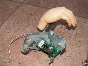
Thing's Hand with motor

Thing's Hand with motor

Received a bargain via eBay today in the form of Thing’s hand with motor. Unfortunately the seller wasn’t sure if the part worked at all, but I still bidded on it.
 
The wires to the motor were cut off and, as the wires to my Thing’s hand motor had already come off (following removal a while back) I simply soldered the original wire plus plug assembly onto my newly acquired hand and tested it.
 
Not only did the coil work, but also the motor. An added bonus is, that this hand looks a lot more “natural” than my old one, as the colour of the hand is more realistic. So I’ll definitely be building this hand plus motor into my restored pinball (when I get that far….)

Flasher Problem solved

Monday, June 15th, 2009

Well, I didn’t have to wait until stripping the playfield as reported in my last post.

I was just checking out the flasher connectors under the playfield today and it turns out the problem was with the 2 pole connector for the Train Flasher. This connector had bad contacts. Having widened the male connector poles of the plug and made the female receptacles tighter in the socket and connected everything back up, the flashers flashed in their full flashing glory!

As the black/red wire from this connector also feeds the Upper Left Ramp Flasher, this flasher also suffered from the bad connection.

If only I had started from this end and worked my way up…..

So I tried out the pinball machine with the “new flashers” and boy did it make a difference! All flashers seemed brighter and the top left hand corner of the playfield was lit up as never before! Fantastic.

It actually gave me such a rush I played a game and after the very first ball I had scored over 53 Million – unprecedented! I finished off the game (yes, I know, after 5 balls) with a new high score of:

173,866,280

WOW!

PinLED Power Board

Sunday, June 14th, 2009

As I mentioned in my previous post, to check the power board, I put in a new one from PinLED.

Since this new power board has been in the pinball machine, however, I’ve noticed that at switch on and switch off, that the display shows a random pattern on the DMD, but very brightly, as if with this power board a spike is getting through to the display board. I’m not sure this can be healthy form my display board, so I’m going to enquire at PinLED what is actually going on.

Flasher Problems – continued

Sunday, June 14th, 2009

I took out my old Power Board yesterday and replaced with a new one I had bought last year from PinLED. I fired up the pinball machine and tested the flasher circuits. Same problem was apparent (maybe I should have tested the pinball with this board before replacing components? Another lesson learned).

So today I rigged up a flasher lamp tester and connected it to the +20V  Test Point on the power board and poked the other end in J126 pins 1 through to 6 in turn (these are the “grounding pins” for the flasher circuits) whilst the lamps+flasher test was in progress.  The test flasher flashed for every pin, which implies to me that everything is working as it should at the board level, but at the playfield level it is somehow getting screwed up.

Whilst prodding about under the playfield I also found a connector which had a red/white wire attached to it (the 20V DC line) as well as the black/red and black/brown wires. These are the “ground” wires for the rear flasher circuits. I disconnected this connector and then tested each flasher. Interestingly only one of the flashers of each pair now flashed (implying to me that each flasher pair is fed from a different 20V DC line from J107 (pins 5 and 6) and that
I had now disconnected one of these feeds).

However, interestingly, during the individual flasher circuit test, when it came to the Left Lightning Bolt/Mini Flipper pair of flashers, both flashed, Also when it came to the Right Lightning Bolt/Swamp Flashers, the Right Lightning Bolt and the Mini Flipper flashers flashed – this should definitely not happen! (With the connector connected again, this phenomena was no longer present).

So something appears really screwed up with the flasher wiring which I just don’t understand……yet. Also, in order to test the flasher circuitry at the playfield end requires the flasher bulbs to be removed. As this is not so easy for three of the flashers, I’ve decided to leave this testing until I’ve started to remove the parts from the playfield (for the renovation).

Flasher problem – replacing some components on the Power board

Friday, June 12th, 2009

Back to my flasher problem today. As reported earlier I’ve got a flasher problem and having enquired on flippermarkt.de and RGP, based on inputs received, decided to replace the 20V supply components (Bridge Rectifier BR4 and Capacitor C11) and also the ground switching circuits for the affected flasher circuits (Transistors Q39 through to Q42). I also took the opportunity to replace the pin connector for the GI lights (J121) on the board, which had been badly burnt in a previous life.

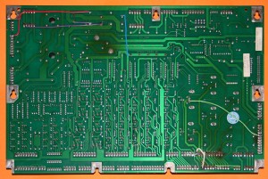
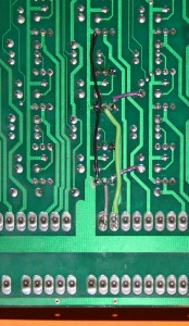
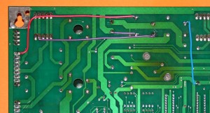
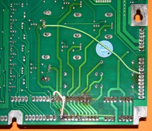
I haven’t desoldered components for a long time and a double sided board makes the job that much harder. I managed to remove all the components, but in the process ruined the through-hole plating in numerous locations – especially around the transistors. So having replaced the components in the board I needed to do some patch work:

The complete patchworked WPC board

The complete patchworked Power board

The patchwork around transistors Q39 to Q42.The TIP102s were the worst affected

The patchwork around transistors Q39 to Q42.The TIP102s were the worst affected

The patchwork around BR4 and C11 - just to be on the safe side!

The patchwork around BR4 and C11 - just to be on the safe side!

Some patchwork to the GI circuitry from a previous life - the green cable is new (mine)

Some patchwork to the GI circuitry from a previous life - the green cable is new (mine)

With all these new components and patches, I was a bit concerned about putting the board back into the pinball machine. But I did and having plugged all the plugs back in to the board, I gingerly switched on – and the pinball worked – a miracle.

So I went straight to the test menu to test my new flashers. First the flashers – yes they all worked and seemed brighter! I was on a high! So I went to the “all lamps and flashers” test and………….

……….nothing had changed!!!!! I had exactly the same problem as before! Well at least I hadn’t broken the Power board!

But let’s look at the positives……I’ve eliminated the supply and ground switching circuits from the equation.

Or have I?

Switch Covers

Thursday, June 11th, 2009
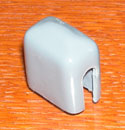
Plastic Switch Cover

Plastic Switch Cover

I’ve been looking for some switch covers for some time. These are to cover the ugly microswitch + diode combinations on both of the ramps, at the entrance gate to each ramp. I’ve seen some examples of these being used on a TAF, but haven’t actually located any to-date.

However I read on RGP today that it is possible to make these covers yourself, the instructions being on this website. Basically it uses plastic which is in a liquid state, but if applied to a solid base as a thin film, dries when exposed to air. To make the switch covers, it is just necessary to produce a form of the right size and then apply several layers of the plastic on the form, by dipping it into the liquid plastic letting it dry and repeating several times until the right thickness is achieved.

Despite the fact that “Plastidip” is an American product it is also available in Europe from Plastidip Deutschland GmbH, so I have ordered some to try out.

Watch this space…

Colour Matching – part 2 – The Apron

Friday, June 5th, 2009

Having ruined my new apron (see post from April) I have decided to attempt to repair the screen printing which I damaged. In order to do this, I’m going to use waterslide decals, which can be printed on my inkjet printer. I’m sure that I could use an easier solution (such as the stick on decals which are available – and which I already have) but having seen such decals live, I hate the way they look. Take a look at this picture, for example:
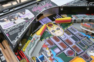
A renovated TAF with stick on apron decals

A renovated TAF with stick on apron decals

Just look at those stick on decals and those edges – yuck!

As I intend to use the waterslide decal on just the Addams Family lettering, I need to match both the purple and white colours. So back to my colour grids from last month. The first thing I noticed was that the purple colour appeared to be a mixture of just cyan and mauve. So I printed a grid of cyan versus mauve with 0% yellow:
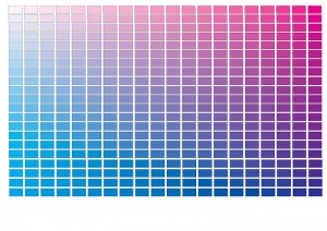
Cyan vs Magenta Colour Grid (0% yellow)

Cyan vs Magenta Colour Grid (0% yellow)

From this, I decide that the best match was with 100% Mauve and 65% Cyan, however the colour was not quite right, so I printed a new colour grid with 100% Mauve and 65% Cyan as the base colour, with different shades of yellow (0 to 40%) and black (0 to 19%):

Colour Grid with 100% Magenta and 65% Cyan

Colour Grid with 100% Magenta and 65% Cyan

From this grid (yes the colours are all different), I selected the 30% yellow and 5% black option. Now onto white.

For white, I assumed that the white colour had been discoloured due to the black gloss paint under the screen print and due to a “yellowing” with age. So I printed out a grid of yellow versus black – and got some great colours of gold but nothing like the colour I was after. So I took a photo of the apron with white printer paper on it (yes, I used the printer paper with “golden” colour grid):
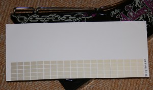
Apron with white printer paper

Apron with white printer paper

I then adjusted the levels of this photo to get a part of the white paper near to the “white” on the apron to have a white CMYK value (all 0%) and then measured the CMYK value of the apron “white” close to my “true white” spot:
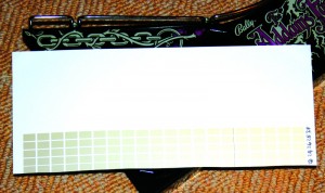
Manipulated photo

Manipulated photo

The value I finished off with for the “white” was Cyan=40%; Magenta=20%; Yellow=35%; Black=0%.

Having printed this out, I still wasn’t happy with either colours so fine-tuned them:
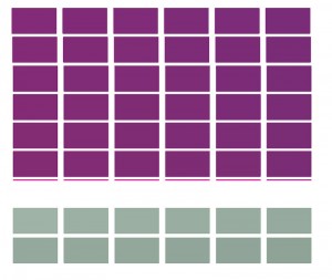
Fine tuning purple and white

Fine tuning purple and white

I finished choosing the following colours:

Purple: Cyan=64%; Magenta=100%; Yellow=30%; Black=5%
White: Cyan=40%; Magenta=20%; Yellow=35%; Black=24%

Which resulted in the following decals:
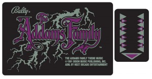
Apron decals adjusted for colour

Apron decals adjusted for colour

Now these may look strange, but I cut out The Addams Family logo from the paper and tried it out “in situ” on the actual apron (by simply placing it over the current logo):
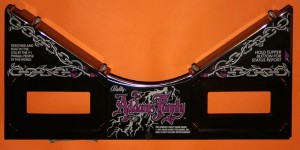
Apron with "new" TAF decal
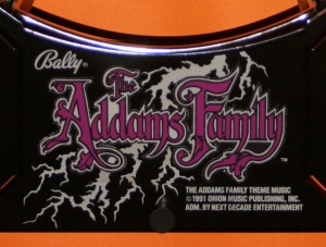
Apron with "new" TAF decal

New TAF "decal" up close

New TAF "decal" up close

Not bad! Although I will have to wait until I print the logo onto the waterslide decal paper to see whether I need any further adjustments.