Finding the culprit
After a couple of days thinking about the opto board, I’m more confused than ever. It turns out that the “overheating” of the diode reported earlier, was in fact the two resistors getting hot to the touch (is this normal for a resistor, rated at 1/2 watt but only dissipating 350mW?)
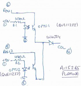
Not being able to find the schematic of the opto board in any of my manuals, or on line, I drew my own.
Whereas I can understand how this circuit works, I can’t tell why a switch connected to the adjacent column of the same row as the opto 2 “switch” should cause the opto 2 switch to effectively turn off (a similar experiment with the adjacent column switch attached to the same row as opto 1 yielded no problem).
Could it be that opto 2 was working at its limits and being affected by the slightest change in current and or voltage at its transistor terminals? Having read on the internet that some variants of the S-1865 opto was susceptible to “gain” issues causing problems in other machines, I though that this might be the problem. So it was time to find a replacement for the S-1865….
It turns out that the S-1865 was made by a company called Senisys, who, it would appear, no longer exist. Further investigations yielded that there is, however, an equivalent from Fairchild Semiconductors called the QVE11233.
A quick look on the internet revealed the data sheet for this part (on Fairchild’s website) and it looked to be the same part, although on closer examination I once again got confused (obviously an easy thing to do): on the opto board, the pcb has a marker on one of the corners of the opto which aligns to a groove on the Senisys device. I assumed this to be pin 1. This also seemed to correspond to the QVE11233 datasheet’s designation of pin 1. However, if this were in fact pin 1, my circuit diagramme would be totally incorrect (with the diode and transistor being swapped) which makes absolutely no sense to me whatsoever. If it were to signify pin 3 (or the pin out on the data sheet is incorrect) however, everything would match with my schematic.
So I’ve now ordered some QVE11233s on the internet to see how they really look like and to try them out.
