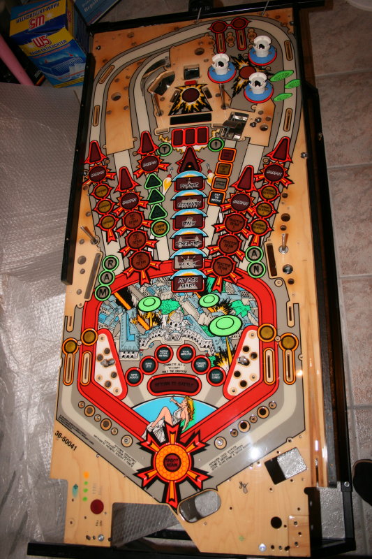
Fitting the legs
Sunday, April 7th, 2013As you know (if you’ve been reading through this blog) I’ve had problems with the decals which I applied to my machine, meaning that for all screws which go directly into the cabinet, I’m having to cut away the underlying decal to stop it from “squashing”.
Famous for causing problems with all decals (not just sub-standard ones, which I appear to have) is the area behind the leg mountings. This area comes under varying amounts of pressure during its lifetime, due to the way pinball machines are played, which decals don’t like. As a result the decals crease in next to no time around the leg mounts. This is also apparent in WPC factory cabinets where decals were used for the first time (most Monster Bash machines for example).
Investigating on line, a solution appears to be, to make a cut in the decal around the leg mount. Well this is what I would have be planning to do anyway (and to remove the cut away part instead of just leaving it on the cabinet – as with the screws).
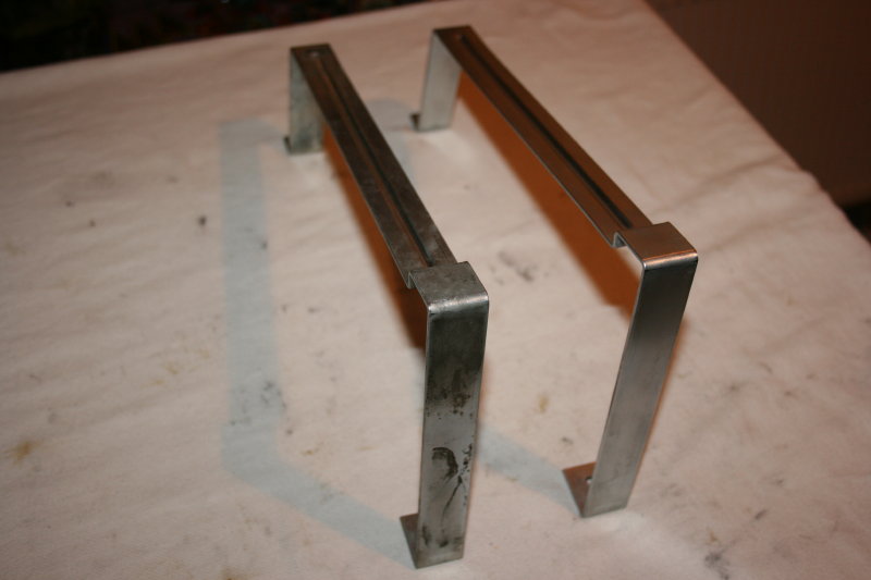
But then I found the new STERN leg mounting plates. I’m guessing that as STERN is using decals now 100% on its newest machines, they’ve had to find a solution to this problem. And I think they just have. The solution appears to be a touch of genius.
It consists of a metal angle plate which fits between the leg and the cabinet. This plate keeps the leg away from the cabinet (and therefore the decal). The plate itself is screwed to the cabinet, thereby preventing any movement and stopping the decals from creasing.
So I purchased a couple of sets to try.
Attaching them was quite straight forward – fitting them onto each corner with the screw provided; cutting away the decal underneath around the edge of the bracket; removing the bracket again in order to remove the decal from underneath and then re-attaching the bracket.
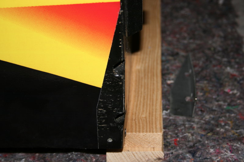
Decal cut away for the bracket
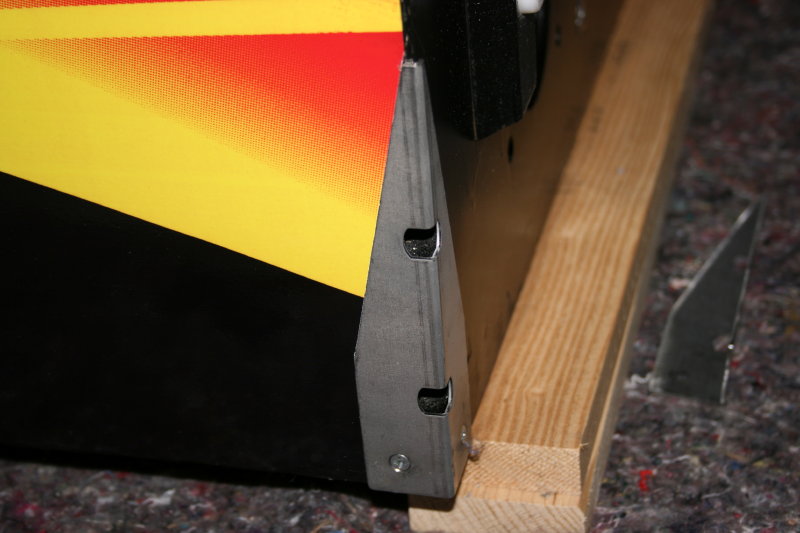
With bracket attached
Mounting the legs onto the cabinet was then pretty straight forward and once they were fitted and tightened, each leg was distanced about half a millimeter from the cabinet thereby preserving the cabinet decal…
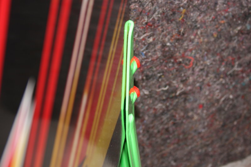
0.5mm clearance from cabinet to leg

Mounted leg – with Martian Eyes
…or so I thought….