When I was 17 I got my first motorbike, a Yamaha RD250LC. There are plenty of stories I could tell related to this wonderful machine, but one struck me today as I was building the remaining pieces back onto my AFM:
It was actually on the day that I was going to advertise my motorbike for sale in the local newspaper. In those day, there was no internet or eBay, meaning I had to ride my motorbike to town to arrange this “for sale” ad. Well as I was on the way to the newspaper’s offices, the engine blew up. Typical.
So with a Hayes Manual (look it up) together with a neighbour and very good friend (thank you John P) I took the motor apart to get at the siezed piston. In the end, I had to take the motor housing with (now welded) pistons and gaskets to the local Yamaha dealer to get it repaired.
After 6 months I got the parts back and so it was time to put the engine back together again. Even though John was no longer anywhere to be seen, I had my Hayes Manual (look it up) and put the engine back together again all by myself. It took me all of two days of solid work. But finally, I got it all back together again. All except a single washer, which was left over. Now this washer obviously came out of the engine somewhere, but where, I hadn’t got a clue. So what should I do? Take the engine apart again to find out where it should go? No way! I decided to just see if the motorbike would start, without the washer. So I put the key in the ignition, turned the machine on and kick started it (no electonic start on machines of that size in those days) and it started first time! It hadn’t done that even when it was working perfectly.
Needless to say I quickly sold the motorbike (minus the washer) and never heard anything back since……
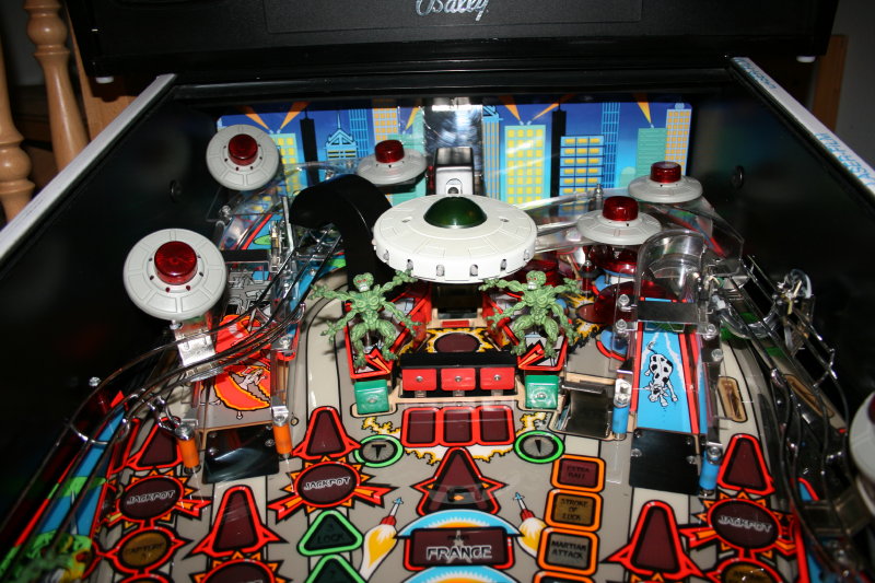
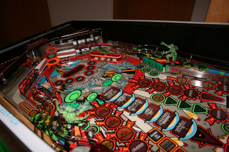
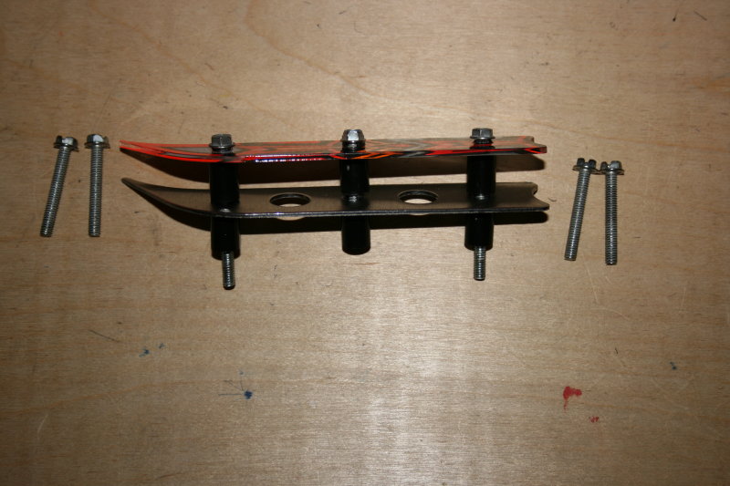
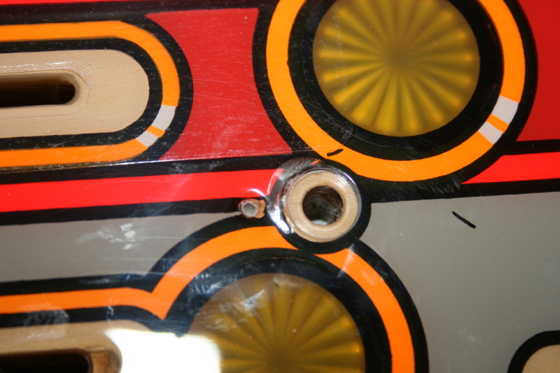
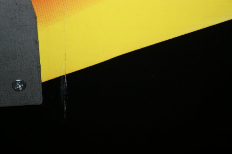
Back to pinball: Having rebuilt all of the bits and pieces on the top of the playfield, it came to the inlane/outlane separator modules (whatever they’re called). Having built these up, I noticed that the screws were of the wrong length. I had only gone and used the correct screws elsewhere in the machine! But where? Aghh! So close to finishing the machine, but yet so far:
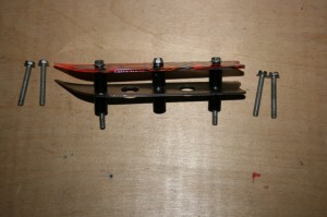
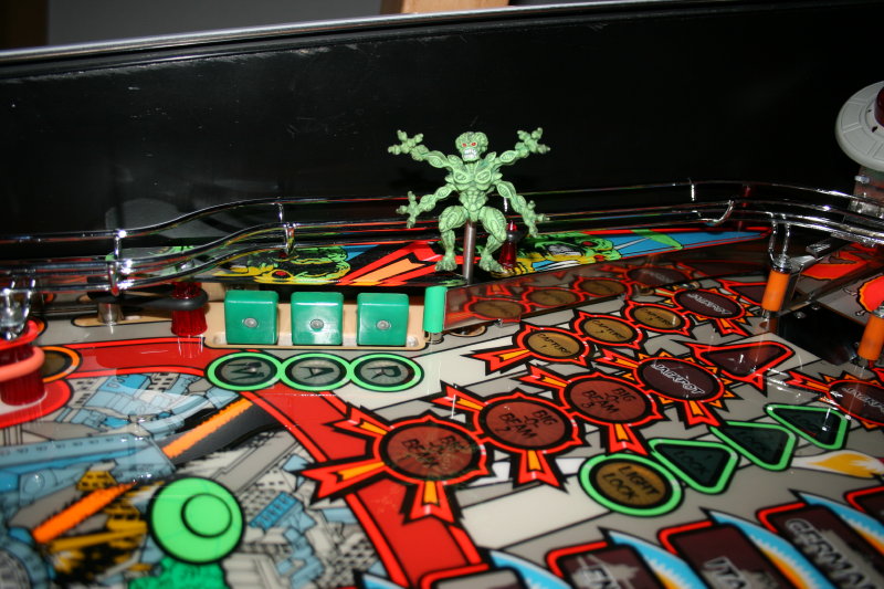
Module with screws which are obviously too short!
It turns out that my Monster Bash had recently arrived for renovation (watch this space) so I took out the screws from the inlane separators from this as a temporary solution and ordered some new screws on line in parallel.
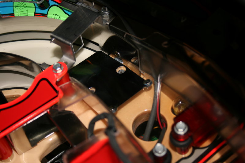
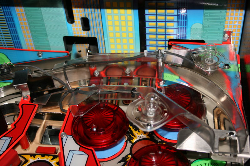
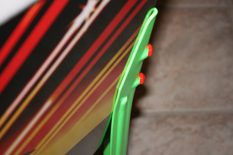
However I was still kicking myself at my stupidity and so deceided to hunt out the correct screws in my AFM which I had obviously installed somewhere in the machine already. Well it turns out I had used two screws in the support brackets and two under the slingshots. So half an hour later and after a little sweat and tears I had swapped the screws out and was able to attach the inlane separators with the correct screws.
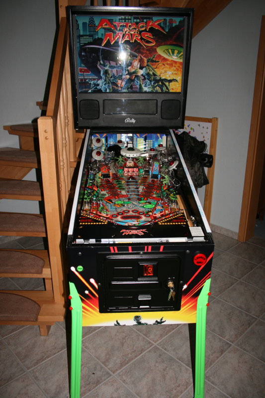
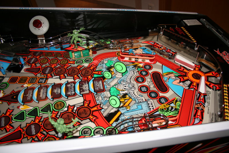
DONE!