Archive for July, 2009

WPC Theory of Operation and Schematics Manual

Friday, July 31st, 2009
WPC Theory of Operation and Schematics Manual

WPC Theory of Operation and Schematics Manual

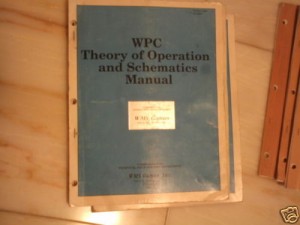
Having read online how invaluable this manual was, even though it was from October 1991 and hence prior to the TAF Pinball  builds, I bought one on-line.

I received the manual today and it was in a good condition. As far as the content is concerned, around three quarters of the information is already available in the TAF operators manual. However there are some interesting sections relating to what could go wrong in the pinball and which component the culprit would most likely be in such an event.

The manual is definitely nice to have, but I’m not sure what value it will add in the future. Let’s see.

More parts

Friday, July 24th, 2009
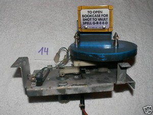
Bookcase with motor and mounting

Bookcase with motor and mounting

Added to my spare parts collection today and acquired three parts:

  • A replacement bookcase plus motor and mounting
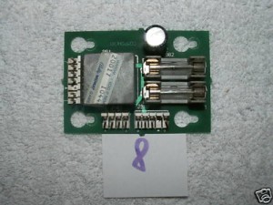
  • A replacement flipper board
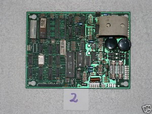
  • A replacement sound board

I attached the bookcase module to my TAF and ran the bookcase tests. The bookcase closed limit switch wasn’t working. After bending the relevant micro-switch lever slightly outwards, however, so that the bookcase cam was actually able to close the switch, everything worked perfectly. The module does need a clean up though…

An original soundboard

An original soundboard

The extra flipper board unique to a TAF pinball

The extra flipper board unique to a TAF pinball

Both the extra flipper board and soundboard both seemed in order, although I haven’t yet had a chance to test them out….

New DMD Driver Board

Saturday, July 18th, 2009
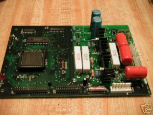
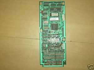
DMD Driver Board

DMD Driver Board

Acquired a brand new DMD Driver Board today. This is part of my continued effort to get replacement boards for all the critical components in my TAF pinball machine.

This particular board was imported from the US, as even with local tax and shipping, this board was cheaper than the equivalent board locally from PinLED!

Plugged the board straight into my TAF and everything worked, as expected. Brilliant!

Am I cheating?

Wednesday, July 15th, 2009

Well with my new MCU board and L7 rom, the game certainly is a little different now: the display for one shows a larger score during play which takes up most of the display. I’ve also notice that the pinballs eject into the shooter lane more smoothly.

An additional adjustment which I had made in the setup menu prior to playing was to award extra balls instead of extra games as rewards. I thought this made more sense, as games are free anyway and awarding extra balls may make the game a little more interesting (if not longer).

So when I played this evening (purely to test the MCU board, you’ll understand) in my very first game, not only did I manage to complete the mansion for the first time, but I once again became Grand Champion, with a score of

337,773,980

Although I was very happy with this, I was left with a strange taste in my mouth, as I’m not sure that with all of these extra balls and a 5 ball set up, it’s not just cheating a little.

Maybe I should revert the game back to 3 ball play with the extra ball setup? Or was this just beginners luck? Let’s wait and see….

Back to my dusty old MCU board

Wednesday, July 15th, 2009

Took another look over the MCU board I bought on Ebay at the beginning of the month which was giving me some erratic behaviour.

I started off by taking the CPU out of its socket, using a small screwdriver in the corner and prising it out gently. I lightly stroked the screwdrive over every contact within the socket and then took the CPU and rubbed each of its sides (where the pins are) over a piece of 1200 grit wet & dry sandpaper (whilst it was dry) to clean the contacts and then inserted the CPU back into the socket (the right way round).

Then, using a sharp knife, I lightly scraped each of the connector pins on the outward facing side of every connector to get rid of any built-up grime.

I then straightened all of the bent component legs on the underside of the board.

I then took my soldering iron and repaired any dodgy looking solder joints – there were a few.

I then took my soldering iron tipped with solder and lightly stroked the tip against the outward facing side of each of the pins on every connector previously scraped with the knife – effectively re-tinning the pins on that side.

I then took out my current MCU board from the pinball and put in this “new” board, pre-loaded with batteries and an L-7 eprom and fired up the machine. And it worked.

I went into the menu and set the time and date, increased the number of balls per game to 5, turned off THING (it’s still not attached – and won’t be until I’ve finished the renovation) and disabled the minimum volume setting. All with no problems.

I then loaded up 10 credits and played a game. It all worked.

Amazing.

I’ve got the bug (again)

Tuesday, July 14th, 2009

I just can’t stop playing my fantastic pinball machine. With all the lights working properly and a “new” upper right flipper the game is that much more exciting.

Sure the new found power of the upper right flipper needs to be harnessed correctly to ensure shots to the left ramp don’t result in “air balls”, but that’s now an added fun part of the game (I guess you could say, you really do need to “feel the power”).

And during Multiball, to know that a ball travelling down the right side of the playfield onto the right flipper will more-likely-than not result in a jackpot is wonderful. I can now get jackpots whilst attempting to ensure that the other pinballs don’t drain (before it just wasn’t worth trying this). Fantastic.

Rebuilding a flipper

Monday, July 13th, 2009

Well I just got fed up of not being able to hit the left ramp. Almost all my shots from the upper right flipper would only make it half-way up the ramp and then fall frustratingly back down the ramp (running more-often-than-not right into the swamp). Only every now and then (with the pinball travelling at an increased speed and being very close to the flipper) could I actually succeed in completing the left ramp. So the possibility of completing the THING lights during a single game (even with 5 pinballs) was impossible (although as I don’t have Thing’s hand installed at the moment, that’s not such a great loss).

So, could I do anything about it? Well looking at the flipper mechanism, everything seemed to be OK; the flipper was adjusted correctly (having done this myself previously) and the plunger moved freely inside the coil. So was the problem with the electronics maybe?

Following my experience with the power board, where I made so many updates to the power board in order to improve the performance of the flashers, but where the problem was purely mechanical (a bad contact in a connector) I decided to take a look at the mechanics of the flipper first.

So it was off to Clay’s Pinball Repair web pages (an indespensible resource) to read up about rebuilding flippers.

I decided to do a quick and dirty disassembly of the flipper. So having loosened the “pawl”, so that I could slide off the crank link assembly from the spindle of the flipper and having detached the spring from the metal base bracket on the bottom of the playfield, I unscrewed the two coil supports from the metal bracket in order to free the coil assembly and the crank link assembly together. Once removed from the metal bracket, the coil assembly and crank link assembly could be easily separated.
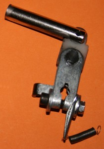
Upper Right Flipper Crank Assembly

Upper Right Flipper Crank Assembly

The coil assembly was interesting. This consisted of the coil itself, a metal bracket on one end and an end stop on the other, all as a single unit. Try as I might, I could not separate the two metal brackets from the coil – and I didn’t want to force them apart. However, from everything I had read on the internet and even the drawings of the flipper assembly in the official Addams Family Operations Manual these should be separate parts. Time for a little brute force….

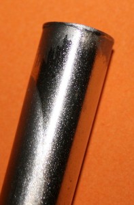
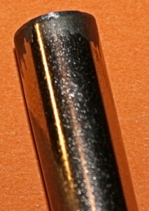
I started with the end stop and used a screwdriver to slowly prise the bracket off of the coil. Eventually I was able to remove the end stop and it was then that I noticed what the problem had been: the end stop had actually mushroomed out so that it was cutting into the coil tubing within the coil and therefore had been difficult to remove. On close inspection of the shaft of the crank link assembly, this also had mushroomed out. Could this have been my problem all along?
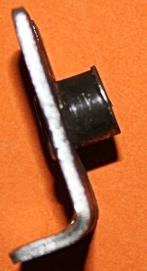
Flared out end stop
Flared out end stop

Flared out end of the flipper shaft

Flared out end of the flipper shaft

Despite the fact that Clay recommends to replace such parts with new pieces, I decide to repair them (basically to see if this was the problem) and so used my new Dremel-equivalent tool to grind down the flaring on both metal pieces:
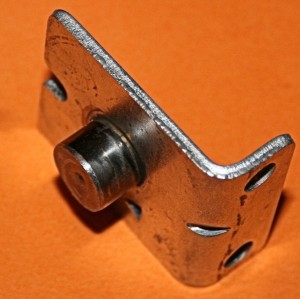
Reworked end stop
Reworked end stop

Reworked shaft

Reworked shaft

It was then time to replace the coil tubing (I had already bought four teflon coil tubes for each of the flipper coils). To insert a tube into the coil required the old (now mis-shapen) metal one to be removed. Unfortunately, this wasn’t easy, as the tubing was stuck in the coil. Fortunately, having taken off the metal bracket at the cable end of the coil, a few millimeters of tubing were left jutting out of the coil. Using a hammer, I hammered this end into the coil, dislodging the tubing from its resting position. This didn’t help a lot, as the tubing was still stuck inside the coil, refusing to budge any further. However, enough of the tubing was now exposed at the other end to enable me to forcefully pull the metal tubing out of the coil with a pair of pliers. In order to do this, however, requires a firm grip of the coil, without damaging it (I managed to remove the outer coil paper in the process, but didn’t harm the wire, fortunately).
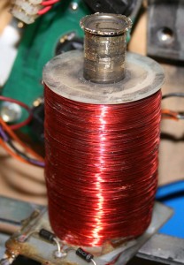
In the process of removing the original tubing. This was harder than it looks!

In the process of removing the original tubing. This was harder than it looks!

Having removed the old coil tubing, the new one just slipped into place quite easily and both the end stop and plunger shaft also moved freely inside the new coil tubing. Wonderful.

Before rebuilding the flipper, I decided to clean all the parts. I used metal polish on all the metal parts and Novus 2 on the plastic parts (including the flipper head, which came up nice and shiny). I also removed the plastic flipper bushing to clean this both inside and out. Don’t be fooled (like I was) that this bushing is simply removed by screwing out the three screws. Behind the bushing are three corresponding nuts.
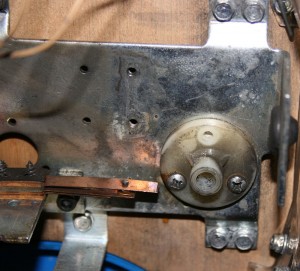
The flipper bushing is secured to the metal base with screws AND NUTS)

The flipper bushing is secured to the metal base with screws AND NUTS)

Of course I realised this too late and had to take off the entire metal base in order to remount the bushing properly. So I took this opportunity to clean the metal base also.

It was now just a case of rebuilding the flipper assembly. This was quite easy really, with the hardest part being to make sure that when the flipper head is in its resting position, that the crank shaft is butting against the rubber stop in the metal base assembly. This is best achieved by tightening the pawl onto the flipper shaft so that it grips, but so that the shaft is still able to move within the pawl. By ensuring that the crank shaft hits the end stop before the flipper head reaches its end position and then forcing the flipper head to its end position ensures the flipper is correctly aligned. The pawl must then be tightened onto the flipper shaft extremely securely.
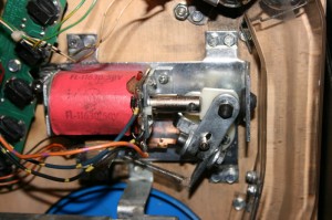
Correctly aligned crank shaft (and a very clean flipper assembly)

Correctly aligned crank shaft (and a very clean flipper assembly)

So did all this effort make any difference? Well all I can say is WOW! Firstly I tested the flipper with a pinball in test mode (by manually rolling a pinball down the side to the upper right flipper and activating the flipper – all from the side of the machine). Not only did the flipper seem more snappy, but it appeared to be no effort at all to shoot the pinball over the left ramp. Excellent. But what about during gameplay?

Well the first thing I noticed is that I could now get to Thing’s Mini Ramp by bouncing a pinball off the post on the right side of the staircase. Also shots to the Train Wreck actually tavelled at the speed of a train making the end plastic visibly shake (I guess some adjustment or protection will be needed here). Finally my very first direct shot to the left ramp resulted in an “air ball” with the pinball not making a complete circuit, but bouncing off the back wall of the ramp back onto the playfield instead. Not an ideal result, but maybe better than not having enough energy to make a complete circuit at all!
Spare Parts

Sunday, July 5th, 2009
MCU Board from an Addams Family

MCU Board from an Addams Family

Received an MCU Board today having won it on eBay. Apparently the board had been working before it was taken out of an Addams Family pinball, but still sold on the understanding that it was “defective” as the seller couldn’t test it.

My first impressions of the board weren’t good: firstly it was very dusty, secondly there were cobwebs on some of the pins. And finally, many of the pins on the connectors were bent. Even the component legs on the rear of the board were bent! To me it seemed that the board had been stacked with other boards for some time in a not-to-clean environment.

So having straightened up the pins, blown off the dust and cobwebs and putting a new L-7 eprom into the board,  I built the board into my pinball. At switch-on the machine fired-up. A good start. But then I tried to play a game, but I couldn’t. The pinball claimed that there weren’t any pinballs in the machine, but there were. This is where the problems started…..

Trying to go into the test menu was a nightmare. Firstly the ‘up’ button wasn’t working; secondly the menu kept on going into the help menu. Eventually I was able to establish that row 7 of the switch matrix wasn’t registering properly (which would go some way to explain why the machine thought there were no balls in the machine, as the outer trough switch – which switches when a ball is ready to be fired into the shooter lane – would not register a ball).

Also the display was acting erratically, with some frames incorrectly displayed and some letters missing.

I haven’t given up here yet (I am still in contact with the vendor) but think (hope?) it could just be a pin-to-pin contact problem.

Building my original MCU Board back into the pinball returned everything back to its normal working state (fortunately). Actually in retrospect, I’m guessing I could have done some damage to my pinball with this board. Thankfully, I didn’t.