Archive for the ‘TAF’ Category

(Yet another) “new” DMD

Thursday, December 4th, 2008

I got my display back today from Stephan Schubert. Yet another different display, this time from Babcock (from 1994). I connected it up and ran the test programme…..

Everything ran wonderfully, all columns and rows were functioning and no “crosstalk” (or “gassing”) from one row or column to another was evident. It was perfect. Thanks Stephan! Although I now had a fully working (and almost aligned) LED based display, there’s something about the plasma display which “fits” better to the pinball, despite its hum. So I’m going to stay with the plasma display and keep the LED based display in reserve.

Stephan also sent me my Tilt weight, spare bulbs and a blue oblong target (with a very strange cap) as agreed.

New plastic ramp

Wednesday, November 19th, 2008

Received a new (used) plastic ramp today.

Bought it on eBay from “reaload” for 33.50 Euro – a real bargain – although I had been a bit sceptical about bidding on the part:

“reaload” is apparently breaking down a TAF at the moment and had a display on offer. With my current situation on my display I thought this would be a good opportunity to get a fully working display. His description seemed very positive, but there was no mention of “gassing”. So I asked the question whether he could confirm that there was no gassing – no reply. Two follow up questions – no reply. I didn’t know why reaload was ignoring me, but I didn’t have a good feeling about it.

So when, at the same time, there was a plastic ramp up for grabs, also from the same seller, I was sceptical. But still went ahead with the bidding process.

Well, having received the part today, I can say that I am totally delighted. No cracks and only slight wear marks where the pinball has travelled. Even the mounting holes are not cracked (like my current plastic ramp). I’m sure that when I’ve polished it with a bit of Novus 3 it will be (almost) like new!

Fault finding Thing’s Opto board

Sunday, November 16th, 2008

Back to the Thing optoboard this evening. I re-attached it to its connector (having used electrical tape to simulate an open Opto 1 switch) and turned the machine on and tested the switches. Sure enough the “left-outlane/Thing-up opto-switch” problem was still evident. However, now that the board was “free” I noticed that by simply moving the board I could get the opto switch to switch temporarily. Maybe this was related to the underlying problem?

I tried to identify which component on the board or wire leading to the board was causing this switching, but couldn’t locate it. Whenever I thought I had, it turned out it wasn’t in fact there. How frustrating! However, I then noticed that the 1N4004 diode on the board was uncomfortably hot! This definitely shouldn’t be the case. This diode (according to its spec) can take 1 Amp. On the board were two 470 ohm resistors, so even though I didn’t have the circuit diagram, I assume (although I may be wrong here) that the maximum current flow through the diode should be 12V/470ohm = 25mA. This shouldn’t cause a diode to overheat. I measured both resistors in situ and measured 470 ohm +/- 5%.

So I desoldered the diode from the board (burning my finger in the process) and measured its resistance in both directions. It seems to be OK, but this overheating is something I don’t like.

So I’ve now ordered some new diodes from Conrad and have tried to get a circuit diagramme of the optoboard from the forum flippertreff.de – but without any success to-date.

Getting Thing’s Opto board out – and the motor and the hand…

Tuesday, November 11th, 2008

I managed to find a tool to remove the grub screw from the interrupter assembly on the Thing optoboard and slid the assembly off of its axis. Now just the two screws holding the board to its mount….

It turns out that these two screws have an inbuilt anti-shake washer, making them near on impossible to remove with the board in situ and the playfield raised. Infact in so doing I had to remove a microswitch and lamp from the playfield bottom in order to get at the screws with a normal screwdriver. Even then it still wasn’t possible for me to remove the screws. And in so doing, I also managed to ruin the screw heads. So now I had no chance of removing this small board without removing the whole Thing motor assembly. So this I did.

Removing the motor assembly wasn’t too difficult, it being held on to the playfield by just four screws. Two of these screws were hexagonal head screws which were easily removed with my newly acquired screwdrivers. The other two screws were standard cross head screws, once again with anti-shake washers. It was in removing these that I developed the necessary technique to remove the screws, namily a jerk and turn motion. Easy.

Having removed all the screws, taking the Thing hand asssembly out of its box was also easy, being careful not to catch any wires whilst removing it (which is easily done) and having removed the plug from the opto board and having separated the cable for the Thing magnet from the cable assembly at the relevant cable connector.

With the Thing hand assmbly now removed, getting at the opto board screws was much easier, but the screws had been really damaged by my earlier attemps to remove them, so I though I might have to drill out the screws. However, on trying my newly discovered technique for removing such screws (jerk and turn), I actually managed to remove both screws even though the cross head on both screws was badly worn!

Now onto the fault finding with the optoboard….

Getting Thing’s Opto board out…

Monday, November 10th, 2008

My Hurly Rivet Tool came today, together with two small bags of rivets. Thank you Richard! Tried it out straight away: wonderful (although the tool did leave a small mark on the rivet head).

Also I worked on the Thing opto board again. This time I established that although the “crosstalk” problem was still evident (the Thing opto up switch turning off whenever the Left outlane switch was activated). No amount of pushing and pulling of the plug to the board or of the board itself would deactivate the opto switch manually. However, having activated the Left outlane switch (so that the Thing opto up switch turned off) by manipulating the opto board, I got the switch to switch on again manually. So, without verifying that the CPU board was not to blame for the error, my next port of call is the opto board. Time to take it off, and therein lies my next problem:

The optoboard is attached to the Thing box bracket with two screws. No difficulty there, but then there’s the interrupter assembly, attached to the motor spindle with a grub screw. This assembly prevents the board from being removed. And I don’t have a tool for the grub screw……yet.

Thing’s Opto switch and the Start button

Sunday, November 9th, 2008

It was back to the spurious Thing opto up switch problem again this weekend (where the Thing opto up switch turns off whenever the Left outlane switch is operated). Having tried to use a multimeter to measure the relevant switch matrix voltages to identify what was happening, I decided that because of the strobing nature of the signals, no sensible results could ever be achieved without the use of an oscilloscope – which is something I don’t have (although I did briefly have one, having succesfully won one on ebay. I had to send it back though, as it wasn’t working as advertised).

At the same time, however, the signal from the Thing opto up switch started to misbehave again, all by itself, showing intermittent shorts. Once again I took the plug off of the Thing opto baord and reseated all the wiring in the plug and reattached the plug to the opto board. Result – no more jittering. And no more “cross talk” between the Thing opto up switch and the Left outlane switch.

But then, the “cross talk” problem suddenly came back again.

Back to the drawing board for this problem. I need to discover whether the problem is with the CPU board or the opto board. Gut feel tells me the opto board at this stage (especially after my short-lived “success” having played with the plug…)

Also cleaned the Start button this weekend. The hardest part here was removing the switch/lamp assembly from the switch housing in order to completely remove the switch housing from the pinball body. The Extra Ball switch which I had bought has a push in and twist locking mechanism for the switch/lamp assembly, but this technique didn’t work at all on my Start button, however hard I tried. And I didn’t want to break the assembly. After much pulling, pushing and twisting, it turned out that the assembly was only push fitted into the housing. So a hard pull managed to free it from the switch housing, thereby enabling me to remove the whole switch, take it completely apart and clean it with soap and water. Reassembley was just as easy and now the switch feels like new!

Trying out a new PinLED display

Tuesday, November 4th, 2008

I returned the faulty display today on the understanding that I would get my old (original) display back, repaired. I am now waiting and hoping the seller is good to his word….Having taken the plasma board out, I built in my newly acquired PinLED LED Based display. Connecting up this board was easy enough with the included cable (and instructions from PinLED’s web-site) and when I switched the pinball on, it looked very good. And the fact that this board was connected to the low voltage (9V) supply meant there wasn’t the normal loud hum eminating from the speakers as with a normal plasma display.

However, despite my first good impressions with this board, it didn’t take me long to notice that the rows and columns weren’t straight. On closer inspection, it turns out that the 128 x 32 display is made up of 16 off 16 pixel by 16 pixel LED modules, and these modules weren’t aligned, meaning that the lines and columns of the display were jagged at the module joints.

So I removed the display to get at the individual modules and embarked on trying to line each module up with its neighbour. To do this, I started from the lower left module and inserted the adjacent module noticing how they aligned. I then took this second module out and inserted it into another area of the board so that there was plenty of room around the module in all directions. I also only inserted the pins just enough, so that they were not fully inserted into the sockets but were just being held by the socket tips. This then gave me the necessary leverage to move the entire module body so that the legs would be bent in the necessary direction whilst ensuring the legs remained aligned. Having performed this bending, it was then just a case of re-inserting it in its original location to see how well it lined up with the other display, repeating the whole process where necessary.

This “alignment” process wasn’t easy and took its time, but the result at the end of the day was worth it, with the display only showing slight mis-alignment.

I’ve been shopping….

Friday, October 31st, 2008

It might seem that I have been neglecting my pinball machine over the last weeks, but on the contrary: I’ve been shopping. So far I’ve ordered the following:

  • Coloured #44, #555 and #906 light bulbs (to see the affect in certain locations)
  • Coloured Flasher covers (to try out different colour combinations in each location)
  • Flasher bases to go with the caps (to replace the riveted Flashers)
  • Playfield wax (to wax the playfield once complete)
  • Target spongue (to replace the missing spongue and to replace the existing spongues where necessary)
  • A blue oblong target (to replace the broken bear target)
  • Plastic protectors (for the sling shots and bookcase plastics)
  • Perspex (to do my own set of target covers and/or plastics…maybe)
  • Mylar (for the target covers)
  • An imperial box-driver set (my metric tools just wouldn’t always work!)
  • Modeller’s wood (to take on some repairs to the cabinet and playfield)
  • 3M double sided tape (this may be needed to stick on my custom target covers)
  • A new bookcase set (to replace the fractured bookcase)
  • A full set of replacement bulbs (just in case)
  • A full set of rubber parts (to replace the current rubbers, which don’t have the right colours)
  • A full set of fuses (just in case)
  • A full set of jet bumper tops (to replace the existing fractured tops)
  • An almost complete set of NOS plastics (to replace the current plastics, which definitely need freshening up)
  • An almost complete set of used plastics (just for the hell of it)
  • Novus 1, 2 and 3 (to assist me in my clean up of the playfiled and plastic parts)
  • 3 new pinballs (to treat my pinball machine)
  • Protectors for all of the out holes (to protect the holes and cover up the damaged areas)
  • Some LED based #555 and #44 lamp replacements (to try out)
  • A set of 18 different coloured acrylic paints (to touch up the playfield, where necessary)
  • 1 ounce of Lightning Blue Paint (to touch up the lightning on the cabinet)
  • Paint brushes (to apply the acrylic paint)
  • A cheap “Dremel” equivalent (to help with the cleaning and polishing)
  • A set of blue steel metal ramps (to replace the existing ramps)
  • A tool-less rivet set (to attach the parts requiring riveting without investing in an expensive riveter)
  • A Hurley Riveter (OK, so I foud a cheap alternative to apply normal rivets)
  • A new shooter (to replaced the current chipped one)
  • 3 slow burn 3A fuses, board and wiring (to update the power circuitry supplying the magnets to prevent future magnet burn)
  • A set of TAF Gold Roms and a “Home” H-4 rom (to try out)
  • An 11 pin Molex plug and pin strip (to replace the burn-out plug and connecting strip -J126- on the power board)
  • An LED based dot-matrix display from PinLED (to try out)
  • A new updated version of the WPC Power Board with modern components from PinLED
  • A new updated Fliptronic I/II board from PinLED (although the TAF will only require the Fliptronic I part, as the equivalent Fliptronic II board is located separately in the back box)
  • A set of four leg protectors in blue (to hide the damaged wood on the main body behind each of the legs)
  • A tumbler (to clean the metal parts of the pinball machine)
  • Decals for the arch and pinball machine front (to replace the damaged decals)
  • Decals for the cloud top (as one of the decals has started to peel off)
  • Decals for the bookcase (as I too am of the opinion that the blue bookcase just doesn’t suit the game)
  • A set of insert decals (don’t know why I bought these really)

More Display Problems

Thursday, October 23rd, 2008
Over the last two weeks I’ve successfully contacted the seller and agreed to have him exchange the faulty dot-matrix display (with columns 127 and 126 not functioning) with a fully functioning one. I received the “new” display today.

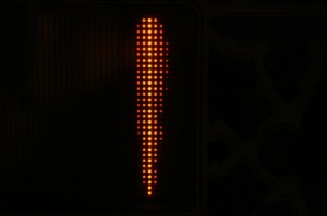
Unfortunately this display was suffering with severe “gassing” making it unsuitable for the display.

An example of severe "gassing" of the Dot-Matrix-Display

An example of severe gassing in the Dot-Matrix-Display

Time to contact the seller again….

More problems…

Saturday, October 4th, 2008
Following the identification of the initial problems reported in my last post, closer inspection has now revealed other issues:

1) The Dot Matrix display has two columns (127 and 128) which aren’t working

2) The blue oblong (bear kicks) target is physically broken
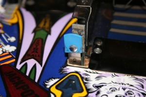
Bear Kick Target

Bear Kick Target

3) One of the two graveyard targets has its spongue padding missing
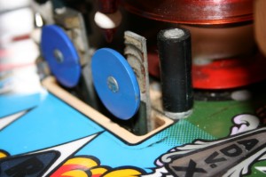
Spongue missing

Spongue missing

4) One of the jet-bumpers (blue) isn’t functioning

5) The jet-bumper plastics are fractured at the mounting holes
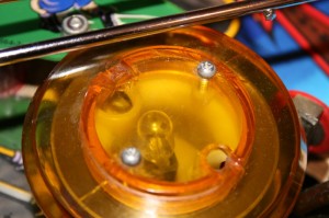
one of the fractured caps (note the repair already carried out)

one of the fractured caps (note the repair already carried out)

6) The plastic (staircase) ramp is fractured at several mounting holes
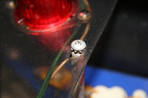
A fracture on the main plastic ramp

A fracture on the main plastic ramp

7) Several of the post-rubbers are old and flaking (in particular the yellow tapered bumper and two of the black rubber sleeves)
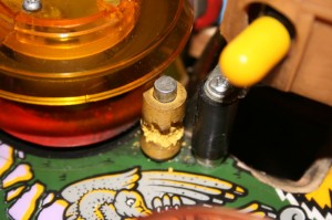
A well worn yellow post
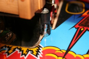
A well worn yellow post

A worn rubber post
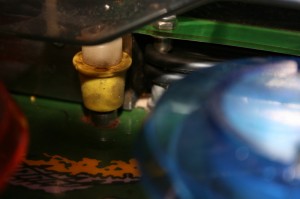
A worn rubber post

Well worn (old) rubber

Well worn (old) rubber

 8) One of the 3/4 inch rubber rings is broken
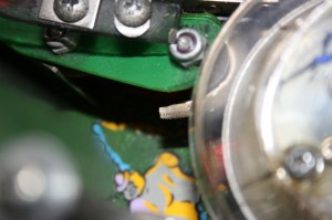
Broken rubber

Broken rubber

9) One of the 3/4 inch rubber rings is completely missing
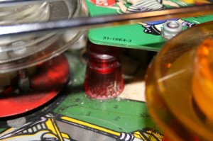
Here was once a rubber

Here was once a rubber

10) Both blue rubber pads on the elevated ramps are missing.
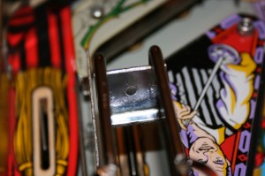
Missing rubber on right ramp ball drop
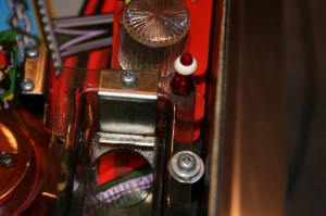
Missing rubber on right ramp ball drop

Missing rubber from left "Thing" ball drop

Missing rubber from left "Thing" ball drop

11) The bookcase is fractured in several places
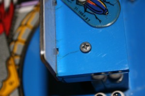
Crack on bookcase
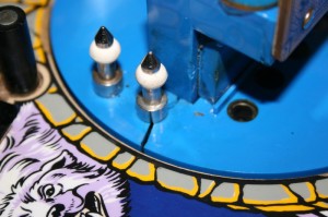
Crack on bookcase

Crack on bookcase plate

Crack on bookcase plate

12) There is evidence of “magnet burn” on the playfield (lower left magnet)

Example of magnet burn

Example of magnet burn

13) Where the playfield would appear to be “burned” some of the paint has flaked away.

Flaking paint under burn (click picture to enlarge)

Flaking paint under burn (click picture to enlarge)

14) The paintwork around the power insert has been worn away

Worn paint to bare wood around The Power insert

Worn paint to bare wood around The Power insert

15) The paintwork under the ramp drop on the right flipper lane is damaged
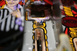
Warn paint to wood under ramp drop on right side

Worn paint to wood under ramp drop on right side

16) The edges of the mylar protecting the playfield have accumulated dirt and don’t look too good
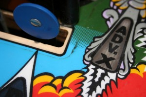
Typical accumulated dirt under Mylar
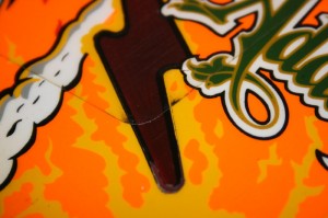
Typical accumulated dirt under Mylar

More dirt under Mylar

More dirt under Mylar

17) The playfield surface around the electric chair hole is severely damaged
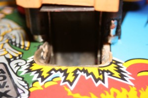
Typically damaged outhole under Uncle Fester's chair

Typically damaged outhole under Uncle Fester's chair

18) The pinball shooter is damaged
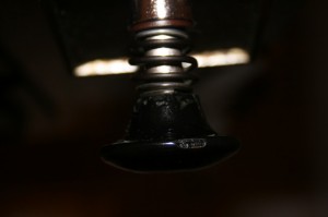
Chipped shooter

Chipped shooter

19) The front of the pinball has paint removed (following removal of stickers, I assume)
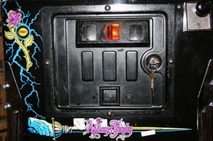
Black paint removed around sword/logo and an extra decal

Black paint removed around sword/logo and an extra decal

20) The transfers on the apron (or bridge or arch) have been worn away badly
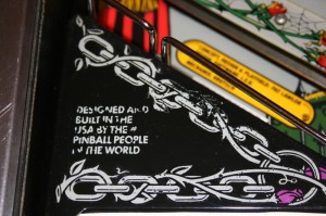
Badly worn decal on right side of arch

Badly worn decal on left side of arch
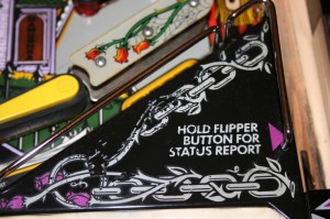
Badly worn decal on right side of arch

Badly worn decal on right side of arch

21) The plastic around the inserts in the mansion is worn away (although this is to be expected in a machine of this age)

The house showing some damage around the inserts

The house showing some damage around the inserts

Considering the description of the pinball on Ebay (see the introduction page) I find it incredible that the pinball has been delivered in this condition. Despite the fact that the pinball I have received is not as described in the auction, the time and effort which I have invested to-date (including getting the pinball machine down into the cellar) make it very difficult for me to return the pinball machine to the seller. As such I have decided to try to work with the seller to alleviate as many of the problems as possible and at the same time to renovate the machine as well as I can.
So let’s get started….