Archive for the ‘AFM’ Category

Re-chroming the ramps

Monday, October 15th, 2012

I got a good deal on re-chroming the ramps and so gave up my ramps to be re-done to a local firm. When I got them back however, the left ramp was a disaster! The surface was all rough and there were many sharp edges on the metal rail which would definitely scratch up pinballs if they were to roll on it! The right ramp was OK though (it actually looked quite good and only had a small bit of uneven texture and a sharp edge which I was able to scratch away with my finger nail).

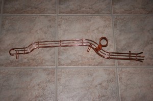
The problem with the left ramp was, apparently, the condition of the underlying steel, which was rusting and pitted. So I agreed with the firm that they would remove all the plating, give me the rail to be sanded down, me to then return the ramp for them to apply the necessary coatings up to the copper coating, which I would then get back from them to sand down again and then return it to the company for chroming:

Copper coated ramp

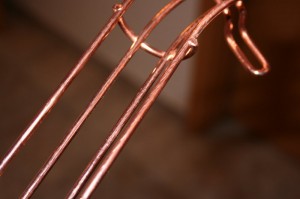
Copper coating in its pre-worked form

After several hours of work, I managed to get most of the copper to a respectable finish

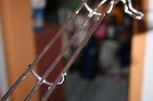
Finished ramp

Considering how the ramp came back after the first time, this is a real improvement!

Disaster strikes yet again!

Saturday, July 7th, 2012

Having completed the ground braid installation today, I was so pleased with my efforts to-date that I thought I’d see how the pinball was looking with the backbox on it. So I carefully took the head and placed it onto the cabinet – my idea being to take a few photos for this blog. But then I noticed something weird.

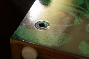
Around the screws which I had put back into the backbox there was a kind of halo:

Delamination of the decal

More delamination

Another example of delamination

I was gutted to say the least!

Removal of the screws and closer inspection revealed that the delamination (ie the detachment of the upper protective layer of the decal from the printed layer) was caused by the pressure of the screw head squeezing the top layer out, whilst holding the printed layer firm.

Delamination caused by squeezing

More squeezing

Delamination rather than rippling

With hindsight and something which I didn’t read or hadn’t found on the net, is that when installing decals, you should only tighten screw finger tight and then a touch more to prevent ripples from forming in the decal. Interesting to note however, that in my instance delamination occured as well as rippling. The reason for this is because of the quality of decals I used. It turns out that I had bought a no-name brand of decals instead of quality ones!

I contacted the supplier of the decals and he promptly exchanged the decals for me – in fact he even offered to re-decal my cabinet and backbox for me as it had been so difficult for me to do. I didn’t take him up on this offer, but instead decided to see whether I could repair this delamination, with the worse case being, that if I wasn’t able to do a good job, I could then re-decal the cabinet and backbox with the new decals.

More on this later….

Ground braid

Tuesday, July 3rd, 2012

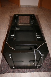
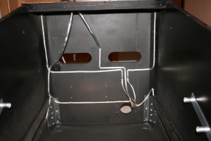
Laid the ground braid today. That wasn’t as easy as it looks, as I had to go through all of my photos of the stripping process to see how to lay it. But I got it done and it turned out well:

Inside of cabinet showing the ground braid.

Ground braid inside cabinet at the back


Moving target bank

Wednesday, June 6th, 2012

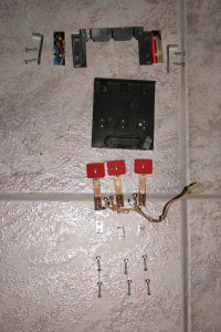
Took the moving target bank apart today, which was much more difficult than it really needed to be. In taking off the screws holding the targets to the backplate,  I stripped the thread on four of the six screws. What a pain!

Broken down target bank - just look at those plastics!

Apparently the target plate sliders break quite regularly. So what do you do when this happens in the wild and you don’t have any replacements. That’s right, cut a playfield plastic to shape and use that instead!

Applying the decals

Monday, May 21st, 2012

I really wasn’t looking forward to applying the decals to the backbox and cabinet. But as always I tried to prepare for the task by asking lots of pinheads for advise and watching numerous YouTube videos prior to starting. Following all of this research, one thing made me really nervous and that was the cutting of the decals having applied them and ensuring straight, uniform edges.

So I started with the backbox. Now I had intended to apply the decals on one side dry and one side “wet” as there are (as always) differing opinions as to which way is best and I wanted to experiment. To prepare for the wet application, I had bought some Rapid-Tac which sounded an ideal solution (pun intended). Having cleaned the first surface with Rapid-Tac, I applied the first side dry.

Rapid- Tac - a vinyl application fluid

Applying the first side dry went so well, however, I skipped doing the second side wet and applied it dry also. I was happy.

Applying the first backbox decal

Using a straight edge to cut the sides was more of a challenge – as anticipated – and although the results weren’t perfect, I was also happy with the results.

But then came the cabinet (which Stephan had helped me carry back down to the cellar)…

Being a decal application professional after my vast experience of two backbox sides, I thought applying the cabinet decals was going to be a doddle. How wrong could I be….

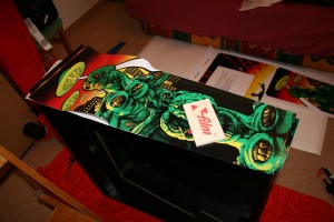
I started with the front decal. Just after starting to apply the decal (and no I didn’t use a blanking plate for the large cut out), I noticed that an air bubble had formed. So I pulled back the decal to expose the air bubble in order to flatten the decal. Unfortunatelay in pulling the decal back, some of the paint was pulled up with the decal and it turns out that on reapplication of the decal, the paint that was removed and on the back of the decal didn’t fall exactly into the surface, where it had been removed from. This meant that having flattened out the air bubble I had left an even more uneven surface than if I had left it alone – arghhhh! And I didn’t learn from my mistake either, as I repeated this mistake three times in total for the front decal alone!

And then, to make matters worse, in cutting out the holes in the decals, I used a scapel and actually managed to cut away some wood from the hole around the start button. How annoying!

Trimming the edges wasn’t as bad as with the head, however, as I had learned that it is possible to do a first cut and then correct any mistakes with a second or even third pass, thereby resulting in an acceptable edge.

By the time I got to the main cabinet decals I was disheartened. After my experience with the front decal I wanted to apply them wet, but couldn’t as I had exposed wood, so I had to apply them dry. This was difficult and each side took me one and a half hours to complete. As I was applying the decals I also had air bubbles. This time, I tried to catch them quickly to get rid of them, without pulling the decal back too far. Any that I had missed I pricked with my scapel and tried to squeeze the air out.

The end result wasn’t perfect – especially considering the amount of time I had invested in total in getting the cabinet finished, but I had got it done and learned a lot on the process.

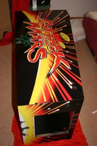
Front and the first side done - looks good from the distance!

Prepping and painting the Cabinet and Backbox

Saturday, May 19th, 2012

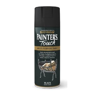
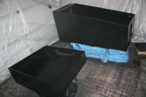
After months and months and months of working on the cabinet and backbox, filling dents and scratches and getting the edges sharp, it was time to spray both parts black with Rustoleum Painters Touch – Silk Black paint (which had been recommended on RPG – albeit in paint form and not in the spray can – as it is a good match to the original satin black colour of the cabinet).

Rustoleum Painters Touch

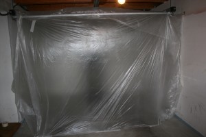
So having isolated an area in the garage and layed down plastic sheeting to form a “spray cabin”  I got Tim to help me transport the cabinet from the cellar to the garage. I then sprayed the backbox, cabinet and backbox screws.

My spray cabin in the garage

The inside of the "spray cabin"

Unfortunately, I’m not the most experienced of sprayers and after my endeavours I had some serious paint runs. So having waited 48 hours for the paint to dry, I rubbed the paint runs down with normal 400 grit sandpaper. Unfortunately, the paint got stuck on the sandpaper, meaning that instaead of sanding, I started scratching the painted surface. So I decide to use 600 grit wet and dry sandpaper instead, wet, which worked much better.

But as I was sanding, as I hadn’t used an undercoat and only had sprayed a thin layer of paint, it didn’t take too long until I had successfully sanded through the paint to the wood. And as I was using water to lubricate the sandpaper (and take the paint dust away) the wood became wet and swelled creating some serious planking. Fortunately as the wood dried out the swelling went down, meaning that the surface wasn’t as rough, but it still wasn’t smooth, with planking, and I couldn’t rub it down further….

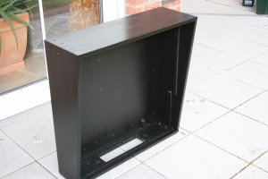
Rubbed down cabinet

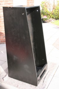
Back Box after spraying - top unfinished, as I ran out of paint!

So what I should have done is to respray the cabinet again with more coats of paint and then rubbed it down again, this time ensuring I didn’t rub down to the bare wood. But unfortunately time  wasn’t on my side and I was running out of spray cans, so I had to leave it and hope.

In hindsight, I should have:

  • used normal paint (ie not out of a spray can)
  • used an undercoat
  • applied a number of coats sanding down between coats

New VUK tube

Saturday, December 3rd, 2011

I finally got my new VUK tube (if that’s what you call it) back from the painters today.

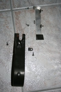
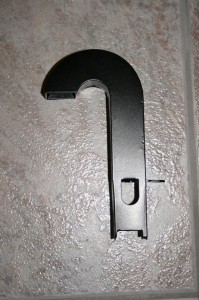
The original was not only rusted and had broken tabs (a common problem with these VUKs) but also had the ball dent in the curve, where the ball slams into the metal when it is shot upwards:

Back of the VUK tube clearly showing the ball dent (and broken tab)

I managed to get a new one from a forum member, which he had made himself. He cleverly made it more rugged with thicker metal, but unfortunately this meant it wouldn’t fit into the assembly under the playfield as it was too big. So I had to file down the outside of the tubing to try to get it to fit into the assembly. This wasn’t easy (as I had to do it manually), took some time and gave me blisters, but at least I got it done!

I then took it to a bicycle paint shop to get it powder coated and this is how it turned out:

New VUK tube showing the filed down base, the thicker metal and powder coating.

But I’m going to have to wait until the whole machine is back together again to see if this actually delivers the ball as expected.

Black lines around the inserts

Sunday, November 6th, 2011

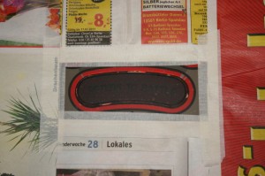
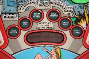
Finished the black lines around the “Return to Duty” and SOL inserts today:

Return To Duty insert ready for painting

New black line

I had to make the lines around the SOL inserts a little wider in order to cover the damage:

Applying the black lines around the SOL inserts

New black lines

More playfield work

Friday, November 4th, 2011

As reported back in June, in trying to level the “Return to Duty” insert with the playfield I applied too much heat and created some delamination. Fortunately I still have the original playfield that was in my AFM and so (having learned from my mistake) was able to take the insert out of that playfield and “insert” it into the new playfield. I used Pattex Repair Extreme to stick the insert into the playfield, following several recommendations from my local forum. To be honest, the first time I had done this was back in July, prior to having the first clearcoat applied. But the insert wasn’t exactly level with the board and the clearcoat and sanding process didn’t bring it sufficiently level, meaning I had to repeat the process today.

Newly applied insert illuminated from behind to test for consistency

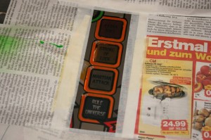
I also finished applying the fluorescent orange colour today. I didn’t use a white background, as I was only trying to accentuate the existing orange colour. The orange colour missing around the SOL inserts exposed a white background, meaning that a white primer wasn’t necessary here either.

Right inlane orange border repainted

Left inlane orange border repainted

SOL inserts' orange borders repainted

In order to cover a little damage, I made the black lines around the SOL inserts slightly thicker than the originals. To check that the thickness of this outline was adequate to cover the damage without them appearing to be too fat, I printed the outline onto a transparent foil and tried it out on the playfield:

Testing the SOL black outlines for size

Black outlines printed on a transparency for testing purposes

In my opinion, this looks just right!

Finished the SOL repair!!

Wednesday, October 12th, 2011

After nearly four months of on-and-off work on the SOL hole, I got it finished today. here’s the process I went through:

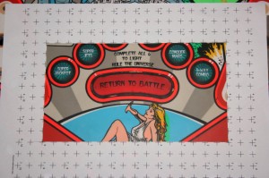
Firstly I wanted to mask off the non-damaged area from the damaged area, so that I could concentrate my efforts on the damage and not worry about damaging good paintwork. In order to do this, I took a photo of the damaged area and used a grid in order to correct the size and perspective in Photoshop and then generate a vector mask to plot on my A4 plotter:
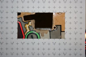
Damaged SOL hole ready for perspective and size correction
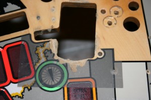
Masked off damaged area

Next step was to fill the damage out with “PC Lumber” and sand it down:
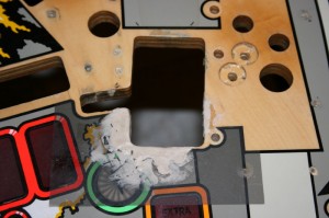
Damaged area filled with "PC Lumber"
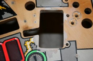
SOL hole with damage repaired

Having finished repairing the damage (not only to the SOL hole, but also the entire playfield) I took the playfield to a local automotive paint shop and got the playfield professionally sprayed with clearcoat and sanded down flat. The results were perfect and just the right platform to start with my paint repairs.

Firstly I had to generate the vector masks for each of the six colours around the SOL hole (black, fluorescent green, white, yellow, light grey and dark grey). Unfortunately with the damage to my SOL hole there was no way of knowing how the original lines had been drawn. My solution was to find a picture of an undamaged SOL hole and superimpose it onto my perspective corrected image, which was the correct size. Boy this was difficult and time consuming, but I got there! From this “master” I was then able to generate masks for each of the colours:
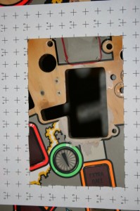
Sanded down damaged area - preparation for vector mask generation
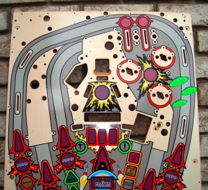
A nice new reproduction playfield
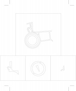
Black, green, white and dark grey masks

Having generated the masks, I commenced with the spray painting of each of the colours, bearing in mind, the fluorescent green would require a white background.

Firstly it was laying down the “wood” colour:
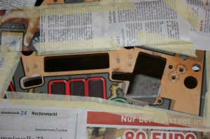
All areas masked off for painting apart from the damaged wood areas
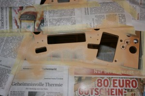
Wood colour applied

Next came the greys, yellow and white:
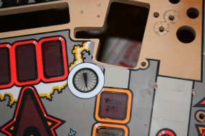
Light and dark greys, white and yellow applied

As always, matching the colours was a pain. I used the yellow I had from my TAF and white wasn’t a problem, but the greys were near on impossible. Using a light grey from my TAF and adding white, black, red and green, I was able to get close to both colours – more by luck than by judgement!

As a test, I next printed the black outline onto a transparency foil and laid that over my work, to check to make sure everything was aligned correctly. I’m glad I did this, becuase sure enough, once I had laid the foil down, I found an error in the yellow/white border. Two new masks and a bit of additional spraying later, I got it sorted out. Phew!
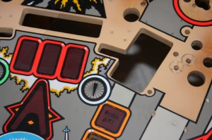
Black line test, showing mistake in white/yellow border
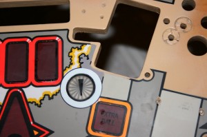
Dark grey and yellow newly applied
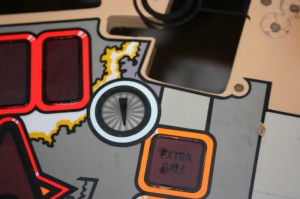
Black line test - everything OK!

Next came an acrylic fluorescent green paint, lightened a little (but not enough, it turns out) to paint the green areas, then the black:
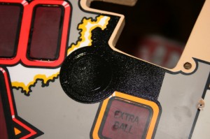
Painting the black borders (outer mask removed)
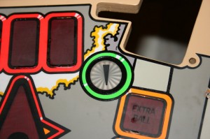
Ta da!

Not bad – even if I do say so myself!